Control box
The control box demonstrates how to use the three pins on the bottom of the BBC micro:bit as digital switches using only crocodile clips. This allows for a simple self-contained device that requires the switches to be interacted with in a particular order.
Key details
- Uses radio group 1 and sends the following messages:
- alarm - triggers the alarm
- diagnostic - places the alarm in diagnostic mode, starting the countdown.
- Buttons A+B - places the alarm is diagnostics mode, disabling the countdown and setting the time to 20 minutes.
Bill of materials
- BBC micro:bit; a V1 micro:bit is fine.
- BBC micro:bit battery power box.
- 3 crocodile clips.
- M3/M4 nuts and bolts to secure the BBC micro:bit and for the crocodile clips.
Either:
- Card or paper to mount the puzzle.
Or:
- 3D printed back plate (here).
- Plastic box with two compartments.
Click here for the completed code.
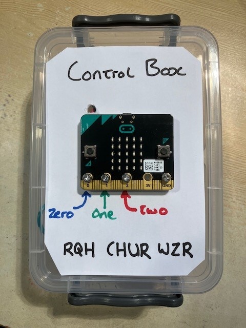
Here is an example of the control box using just paper and screws for the stand.

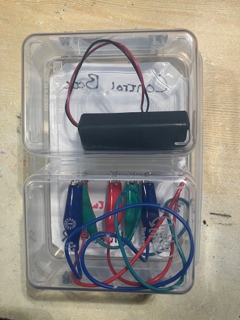
Here is an example of the control box using a 3D printed back plate (here) mounted to a two compartment plastic box.
Explanation
The first thing the code does is change the settings of the pins 0, 1 and 2 so
that they "pull up". What this means is that the pins will naturally have a value
of 1 when read. The opposite of "pull up" is "pull down" which reverses this and means
the pins will naturally have a value of 0. If a pin is neither in "pull up" nor
"pull down" mode then the value of the pins will float around and could be either 0, 1
or somewhere in between.
As the pins are set to pull-up, they will default to 1. However, if we connect one of
those pins to the GND pin, this will force the pin to a low state; i.e. zero. When
the pin is disconnected from the GND pin, it will naturally return to the pull-up state
of 1. The pin can therefore be used as a switch. When connected to GND it has value
0 and when not connected to anything it has value 1.
We can use these facts to determine the order that the pins are disconnected from the
GND pin, allowing us to make a simple puzzle.
To make it easier to connect the crocodile clips to the pins, use long-ish nuts and bots through the holes of the respective pins.
When the control box is running and monitoring the pins, it flashes the centre LED in the matrix on and off.
Before the player disconnects the crocodile clips, they must first solve the caesar cipher. The control box needs to be put into diagnostics mode by pressing the A and B buttons together. The LED screen will show a D. At this point the user has 5 seconds to disconnect the crocodile clips in the correct order.
Get the order wrong or take too long and the alarm will be triggered.
Instructions
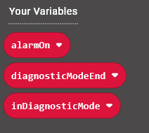
Setup the following variables:
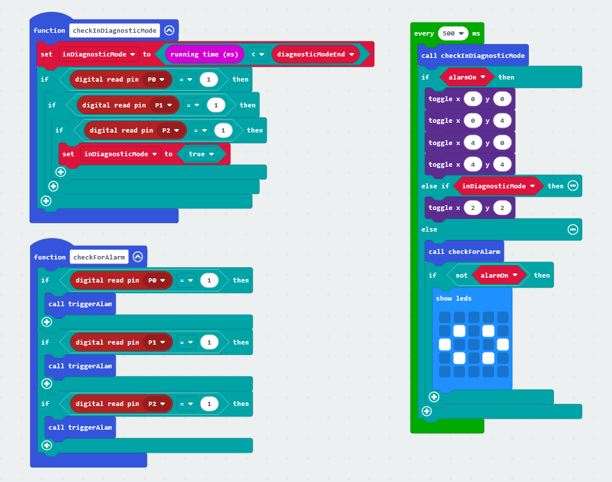
Add the following code:
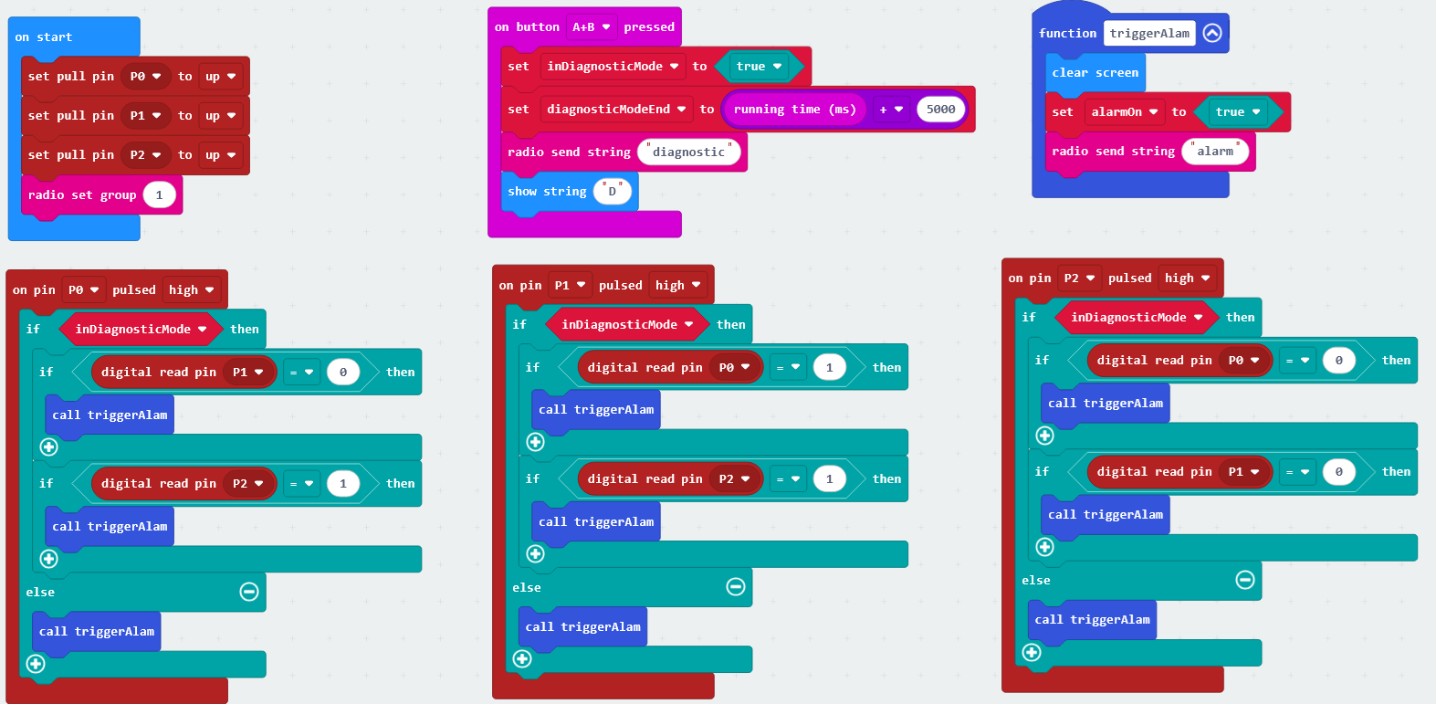
Add the following code:
Solution
The crocodile clips should be removed in the following order: 1, 0, 2.
The clue provided uses a simple Caesar cipher to encode the text forms of the words
ONE ZERO TWO as RQH CHUR WZR. Encoding is done by selecting a letter from the
top line and using the letter from directly underneath it. Decoding is done the opposite
way by selecting a letter from the bottom line and using the letter directly above it.
Caesar cipher
A B C D E F G H I J K L M N O P Q R S T U V W X Y Z
D E F G H I J K L M N O P Q R S T U V W X Y Z A B C
ONEbecomesRQHZERObecomesCHURTWObecomesWZR