Locked door
The door lock demonstrates how to receive binary data over 2 wires between different MakeCode devices (BBC micro:bit from MakeCode Arcade in this instance). This is a simplified variant of the method that only receives the values 0, 1, 2 and 3. A more comprehensive implementation that receives all 16 hexadecimal codes 0 to F is also available but requires a bit more coding so was not used in this example.
This is a moderately complicated part of the escape room.
Key details
- Uses radio group 1 and sends the following message:
- alarm - triggers the alarm
Bill of materials
- BBC micro:bit; a V1 micro:bit is fine.
- BBC micro:bit battery power box.
- M3/M4 nuts and bolts to secure the BBC micro:bit and for the crocodile clips.
Either:
- Card or paper to mount the puzzle.
Or:
- 3D printed back plate (here).
- Plastic box with two compartments.
Click here for the completed code.
If you are doing this escape room with younger children (or have difficulty with the data being transmitted over the wire), use this version of the code which will not trigger the alarm if the code gets transmitted incorrectly
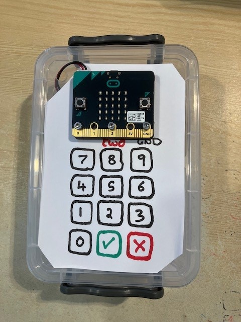
Here is an example of the door lock using just paper and screws for the stand.

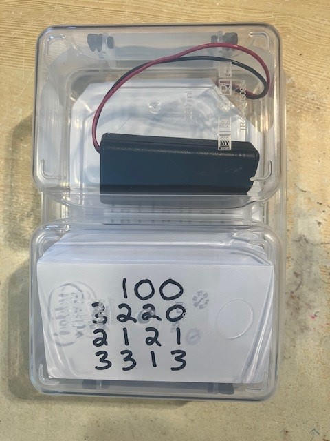
Here is an example of the door lock using a 3D printed back plate (here) mounted to a two compartment plastic box.
Explanation
The door lock can be disabled if a 15-digit code that consists of the numbers zero
through to three is transmitted to the door lock via the 2 and GND pins. Those
15-digits are transmitted over the wire connected to pin 2. Using a technique similar
to that employed in the control box, pin 2 is set
to pull-up (i.e. digital logic level 1). Another device is then connected to pin 2
which will then send pulses down the wire by pulling the the wire down to digital logic
level 0 for a short period before letting it naturally return to 1.
The technique used in this project is that a zero is transmitted by a short pulse (pulled down to 0), and a 1 is transmitted by a longer pulse (also pulled down to 0). To allow for a reasonable error margin, the longer pulse is expected to be 3 times the length of the short pulse. Between each bit of data that is transmitted, the digital logic level needs to return to 1 to signal the bit has finished being transmitted. This is all illustrated in the diagram below:

In binary, two bits can be used to represent 4 different numbers as follows.
- 00 - zero
- 01 - one
- 10 - two
- 11 - three
We can use this principle to send multiple numbers in the range of zero to three between two communicating devices using a sequence of 2 bits.
- 2 bits allows 1 number to be transmitted
- 4 bits allows 2 numbers to be transmitted
- 6 bits allows 3 numbers to be transmitted
- 8 bits allows 4 numbers to be transmitted
- 10 bits allows 5 numbers to be transmitted
- and so on...
Therefore, to send 15 different numbers from zero to three from one device to another, we need 30 bits of information to be transmitted.
Receiving the signal (as is done in the door lock) is the reverse of transmitting. The BBC micro:bit monitors the logic levels to convert the changes to pulses and then determine if they are short or long pulses. The pulses are then converted to their bit representations ( zero or one) and then combined in 2-bit segments to be converted to the numbers zero, one, two or three.
The BBC micro:bit starts recording data as soon as it first detects pin 2 is pulled down
to logic level 0. The BBC micro:bit stops recording after it has remained high at logic
level 1 for longer than 2 seconds (2,000 milliseconds).
If the received code does not match the expected code then the alarm is triggered.
Instructions
Setup the following variables:

Add the following code:
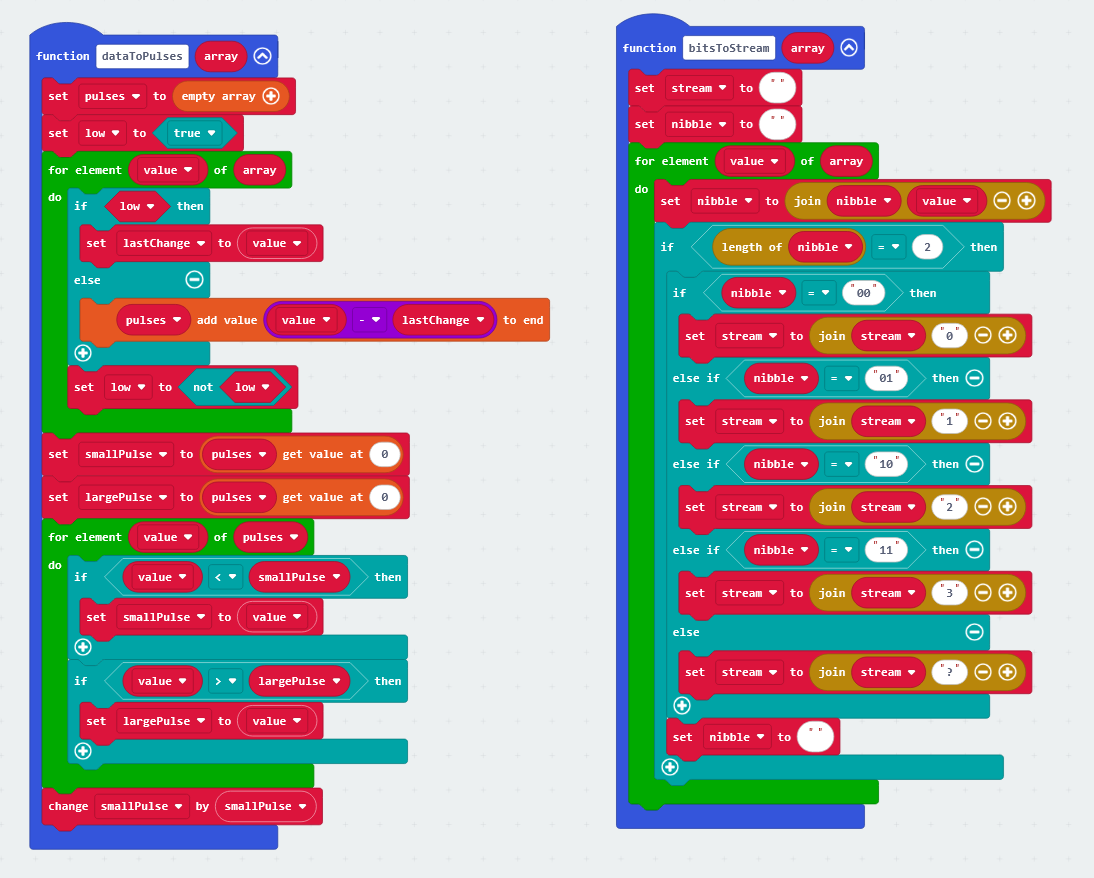
Add the following code:
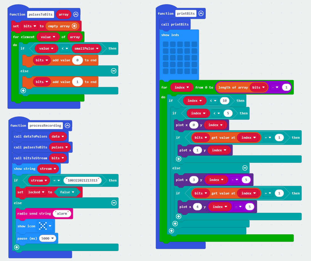
Add the following code:
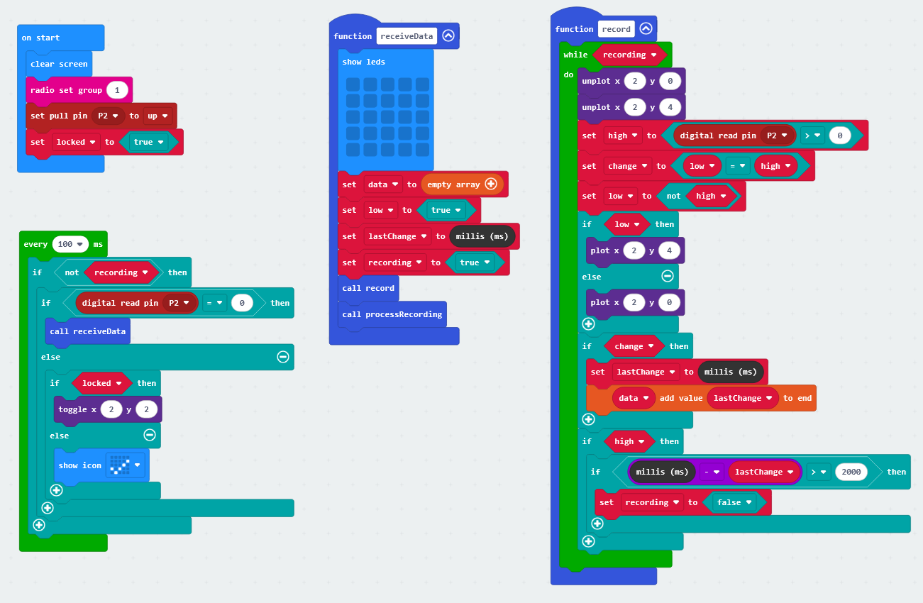
Solution
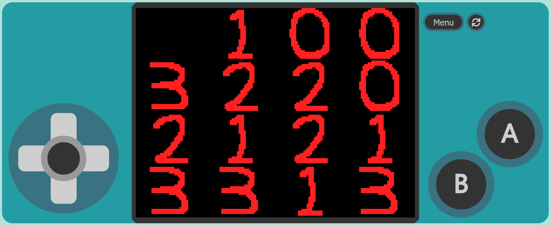
The code that needs to be transmitted should be: 100 3220 2121 3313
On the Door Code Cracking device this will look like this:
