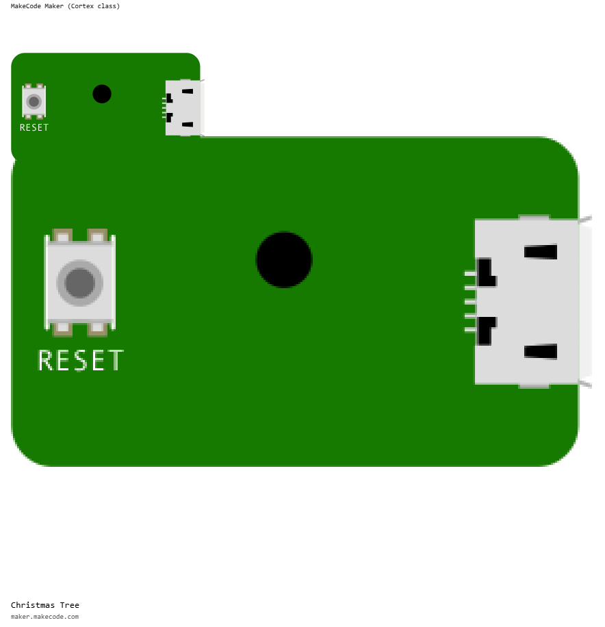
Christmas Tree - MakeCode Maker version
There is a variation of this project that uses CircuitPython which can be found at CircuitPython Christmas Tree.
These materials were created for the Christmas 2025 project and creates a Christmas Tree with a white LED for the star and four additional rows of LEDs on each of the "layers" of the tree. The star is permanently on but each of the other LEDs are individually controllable using code written with MakeCode Maker.
This project will take you through the steps to create some effects with the LEDs. You can then use what you have learnt to create your own dazzling sequence of events.
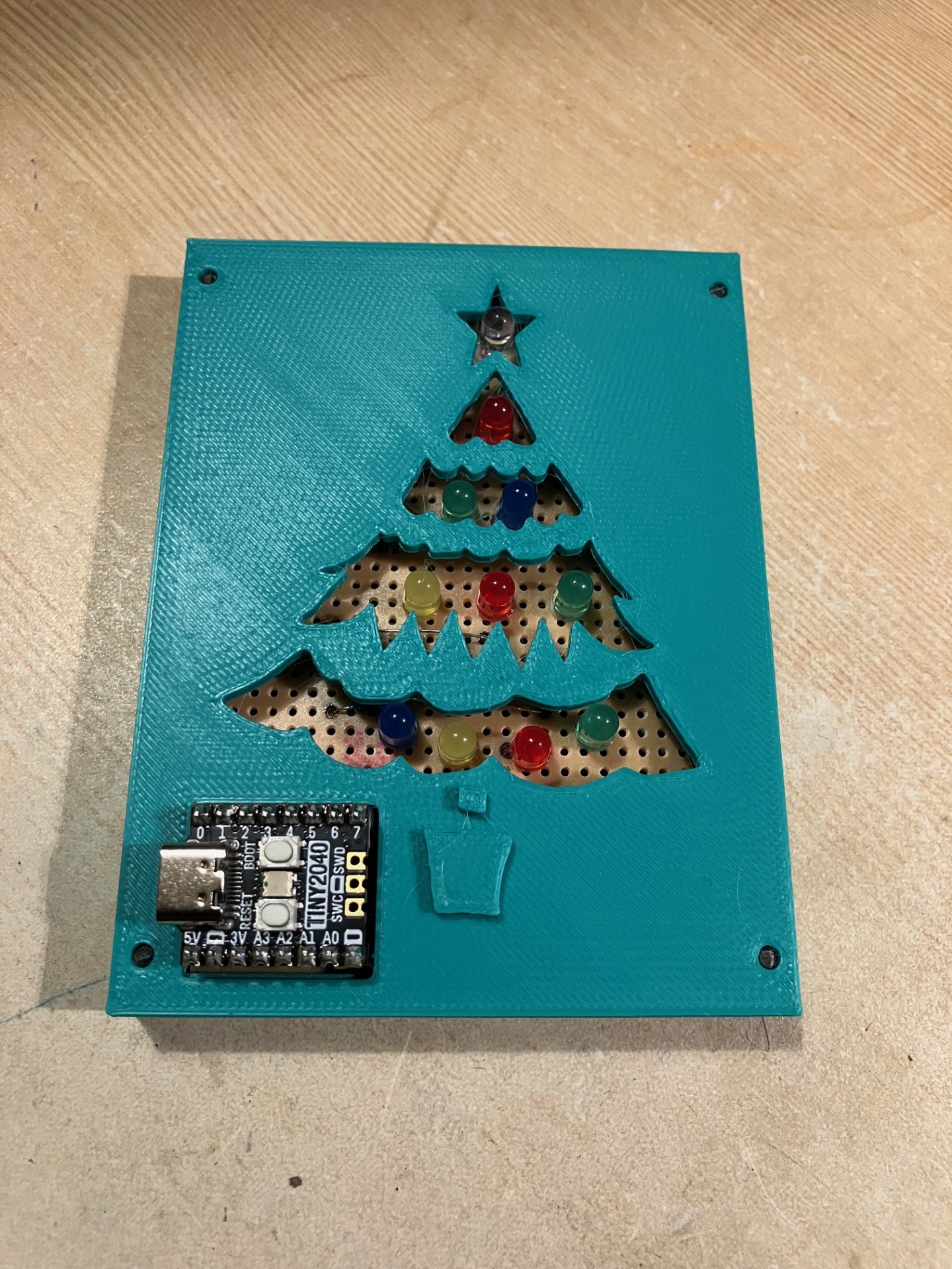
The layout of the LEDs on the Christmas Tree is as follows:
| Tree Layer | Colour, Pin | Colour, Pin | Colour, Pin | Colour, Pin |
|---|---|---|---|---|
| Star | White, 3v3 (always on) |
|||
| Top row | Red, P2 |
|||
| Second row | Green, P1 |
Blue, P4 |
||
| Third row | Yellow, P27 |
Red, P3 |
Green, P6 |
|
| Bottom row | Blue, P0 |
Yellow, P26 |
Red, P5 |
Green, P7 |
Step 1 - Create a MakeCode Maker project
Navigate to the MakeCode Maker website at the following address
https://maker.makecode.com and create a new project called Christmas Tree using a
Raspberry Pi Pico as the microcontroller as shown below:
The user interface of MakeCode Maker will be familiar to anyone who has used one of the other MakeCode platforms such as MakeCode Arcade or MakeCode for micro:bit.
Step 2 - Blink an individual LED
The completed code for this step is available as png or uf2.
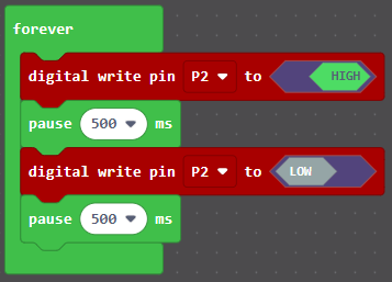
In this step we will make the red LED in the top row blink. This LED is connected to
the P2 pin on the microcontroller. Turning the LED on is done by setting the 'P2' pin
to HIGH. This sets the pin to an output voltage of 3.3 volts (otherwise known as 3v3)
and represents the digital value 1. Turning the LED off is done by setting the P2 pin
to LOW. This sets the pin to an output voltage of 0 volts and represents the digital
value 0. By alternating the P2 pin between HIGH and LOW states with a pause between
the transitions, we can make the LED blink.
The completed code:
Experiment: Change the blink speed
Experiment by changing the duration of both pause statements and observe what
happens. Good values to try are:
- 100 ms
- 200 ms
- 1 second
Reset the two pause statements back to 500 ms and experiment changing just the
first pause value. Observe what happens. Good values to try are:
- 100 ms
- 200 ms
- 1 second
Reset the two pause statements back to 500 ms and experiment changing just the
second pause value. Observe what happens. Good values to try are:
- 100 ms
- 200 ms
- 1 second
Step 3 - Make an LED flicker
The completed code for this step is available as png or uf2.
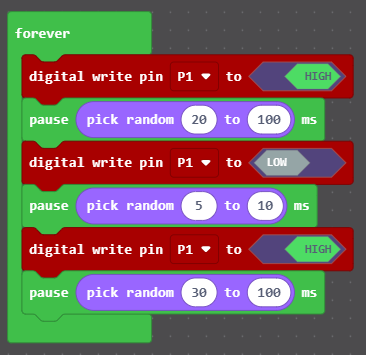
In this step, we are going to make the green LED on the second row flicker. This LED is
connected to pin P1 on the microcontroller. The flicker affect is achieved through a
variation of the blinking code with some randomness added in. This randomness provides a
none regular blink which is what creates the flicker effect.
The completed code:
Experiment: Change the the flicker pauses
Modify your code to make the blue LED on the second row flicker. This blue LED is
connected to the P4 pin on the microcontroller. Start by using different values for the
first pause and observe what happens. Good values to try are:
- 0 and 200
- 10 and 50
- 50 and 100
Experiment with different values for the second pause and observe what happens. Good
values to try are:
- 0 and 5
- 10 and 50
Experiment with different values for the third pause and observe what happens. Good
values to try are:
- 0 and 200
- 10 and 50
- 50 and 100
Experiment: Remove the third digital write
What happens when you take the third digital write pin and third pause blocks out?
Try it and observe how it changes the effect. Can you modify the remaining statements
to get a satisfactory flicker effect?
Step 4 - Make an LED dimmer
The completed code for this step is available as png or uf2.
In the previous steps, we have been using the pause block to add a timing delay between
changing the states of the LEDs. That block takes a parameter which represents the number
of milliseconds to pause. There are 1,000 milliseconds in a second. Even though a millisecond
represents such a small amount of time, using the pause block even with a small number of
milliseconds will produce a noticeable flicker.
When dimming LEDs, we do not want any flicker, we just want a shorter delay. In this case
we can use a different block called wait which also takes a parameter. Rather than
milliseconds, the parameter to wait represents a microsecond. A microsecond is one
millionth of a second. Yes that's right there are 1,000,000 microseconds in a second.
This gives us a finer level of control as 1,000 microseconds is equivalent to 1 millisecond.
In this step you will experiment with using wait to control the brightness of the three
LEDs on the third row of the tree. Yellow on pin P27, red on pin P3 and green on P6.
The completed code:
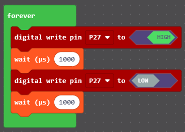
Making it dimmer
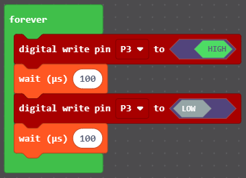
Now add the following code which to dim the red LED on pin P3. How have the different
values affected the dimness compared to the yellow LED?
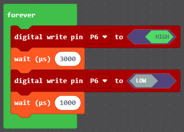
Making it brighter
Now add the following code which to dim the green LED on pin P6. In this example
the amount of time the LED spends on is much longer than the amount of time it
spends off and therefore the LED appears brighter.
Experiment: Modify the timings
Experiment by modifying the timings for the three LEDs and observe what happens. Some good examples to try are:
- 100, 300
- 300, 100
- 50, 50
- 1, 100
- 100, 1
Experiment: Longer timings
Experiment using much longer timings like 1,000,000 microseconds (1 second). How does this impact the other LEDs on the Christmas Tree?
The cause of this behaviour is because wait is a blocking operation that stops the
microprocessor from executing other tasks whereas pause is non-blocking and does
not stop the other tasks from executing.
Step 5 - Make the bottom row chase
The completed code for this step is available as png or uf2.
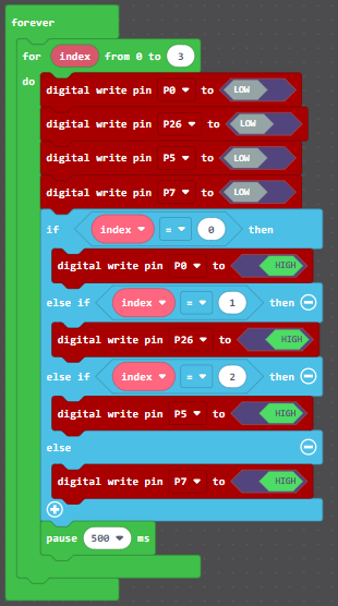
In this step we will animate a chase effect on the bottom row of the Christmas Tree. The chase effect will light a single LED at a time with the illuminated LED moving from left to right and then back again. The LEDs on the bottom row from left to right are:
- *Blue, pin
P0 - Yellow, pin
P26 - Red, pin
P5 - Green, pin
P7
The completed code:
Experiment: Change the speed of the chase
Make the chase effect go faster and slower by adjusting the value of the parameter
used in pause. Observe the effect that bigger or smaller numbers have. Good examples
to try are:
- 10 ms
- 100 ms
- 200 ms
- 1 second
- 5 seconds
Experiment: Reverse the chase
Currently, the direction of the chase is from left to right. Can you make it chase from right to left instead?
Experiment: Bounce the chase
Currently, the chase pattern goes from one side to the other and then goes back to the start to chase again. Can you change the code so it instead reverses direction? That is, the chase goes from left to right, then when it reaches the rightmost LED it reverses direction and goes from right to left.
Step 6 - The Tiny 2040 LEDs
The completed code for this step is available as png or uf2.
The Pimoroni Tiny 2040 microcontroller also has 3 LEDs built into it. These 3 LEDs are very small and close to each other. Therefore, when used together they can make a wide variety of colours.
These LEDs are controlled in a slightly different way to the other LEDs on the Christmas Tree. The Christmas Tree LEDs are turned on using a digital high signal and turned off using a digital low signal. The LEDs in the microcontroller use an active low method which turns them on when the signal is low and turns them off when the signal is high.
The LEDs and their pins are:
- Blue, pin
P20 - Green, pin
P19 - Red, pin
P18
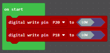
The following code snippets demonstrate how to make some colours.
Purple
The colour purple can be created by turning on the red and blue LEDs at the same time as in the following example:
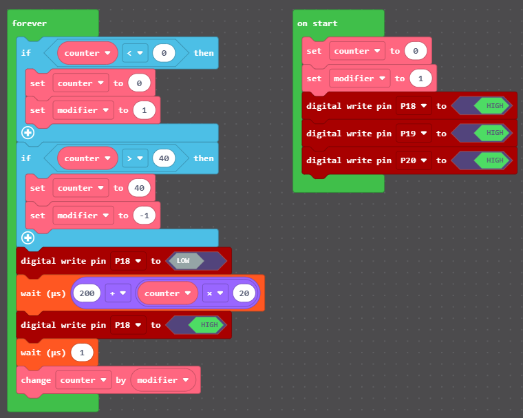
Pulsing red
Replacing the code for the purple LED with the code below will animate the red LED
to pulse. This code requires creating the two variables counter and modifier which
are used to control the length of time the LED is on programmatically.
Experiment: Cycle the colours
Experiment with the microcontroller LEDs to create a range of colours that you like. Can you create a pretty animation by cycling through the colours?
Step 7: Create your own animations
Using the techniques you have learned in the previous steps, create your own Christmas Tree animation. Some examples to consider are:
- Make a chase pattern that runs across all of the rows of the Christmas Tree
- Alternate which colour LEDs are illuminated on the Christmas Tree
- Make all of the LEDs flicker
- Randomly turn on and off LEDs
Making the Christmas Trees
Bill of Materials
The following are the resources required to make this project.
STL file for 3D printing the Christmas Tree. This includes an additional top with a circular hole for a speaker.
64mm x 95mm copper strip board
Pimoroni Tiny 2040 microcontroller
Test program
MakeCode Maker LED test program - png
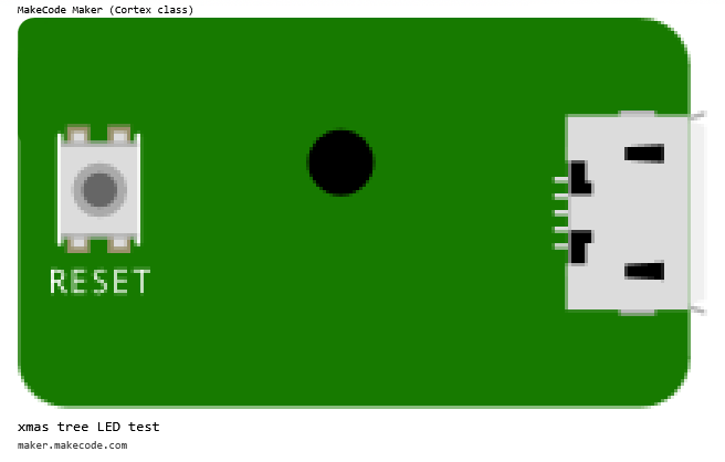
MakeCode Maker LED test program - uf2
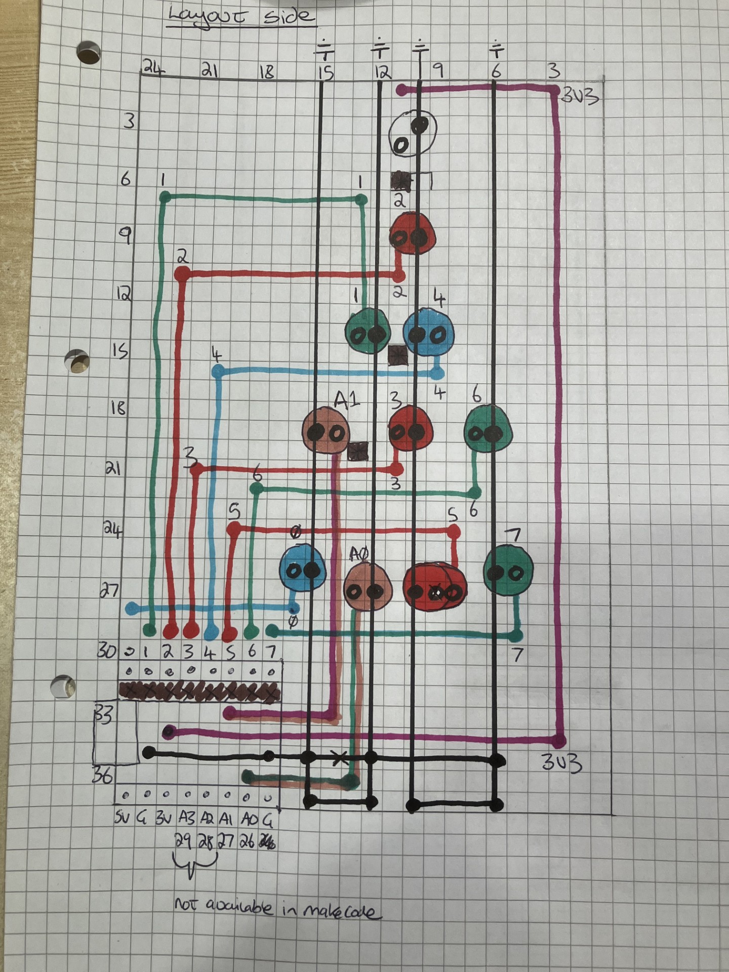
Wiring and assembly
Outline wiring diagram showing the placement of the LEDs on the circuit board. Please note that the horizontal lines are typically connected using a 200 ohm resistor.
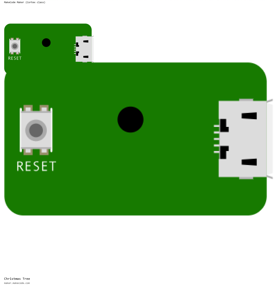
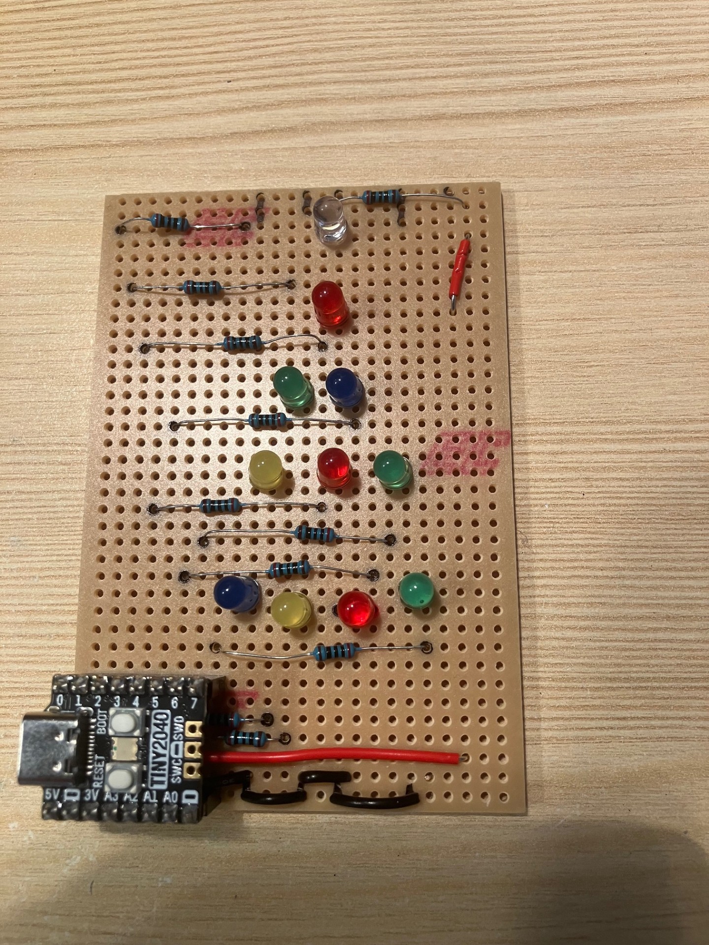
An image of the finished circuit board prior to assembly.
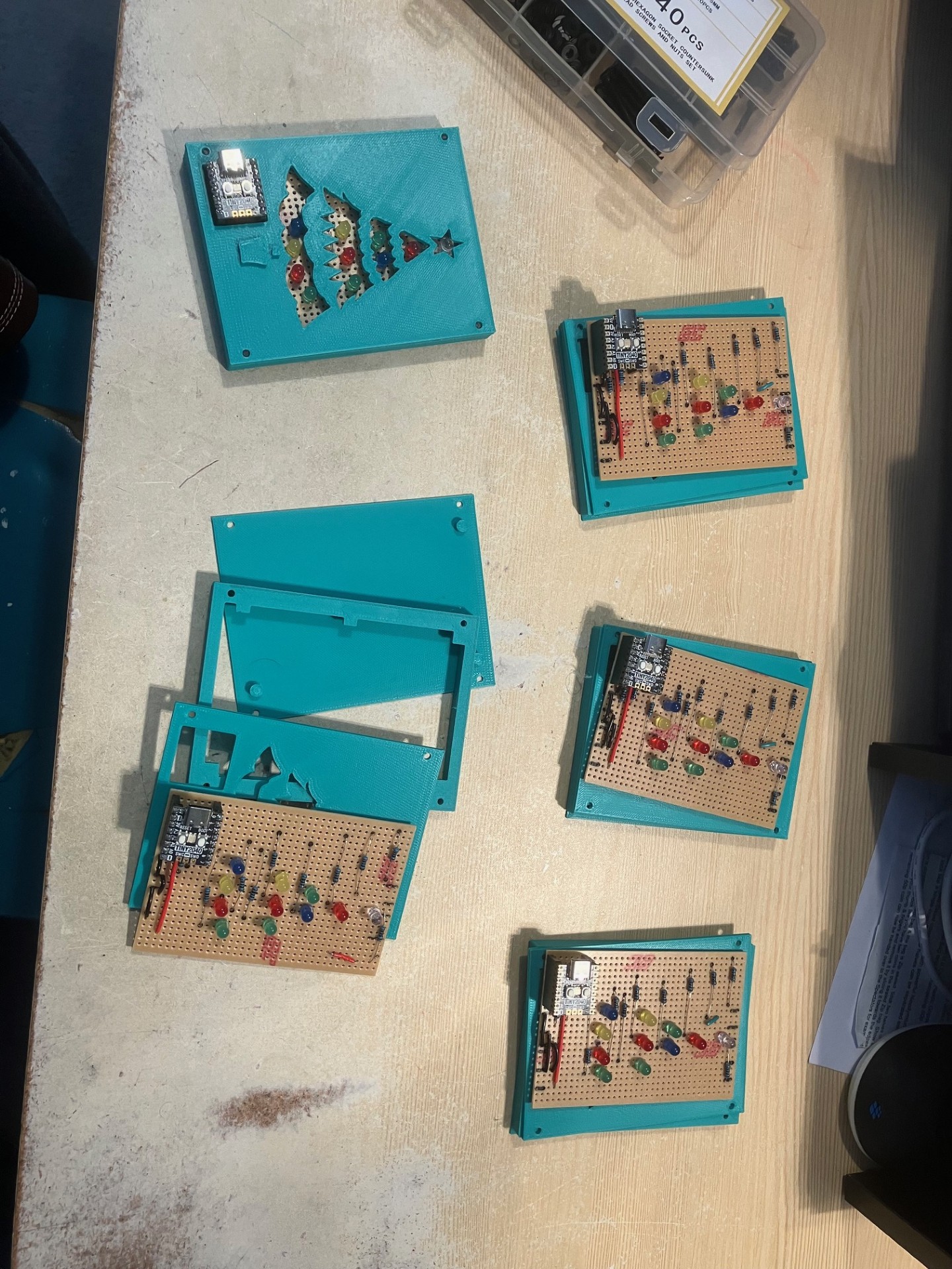
The production line of Christmas Trees in production.